|
The
Art Of
Motion Control
|
The "Dental" mills:
At 3M's monthly equipment auction in August of 2001, I spotted what appeared to be two identical 3-axis mills. While not unusual to find these sorts of devices at the auctions, the fact that they weighed less than a ton was. Although I could see that X and Y travels were limited to only ~4", when I opened the cabinet back, I was greeted by a welcome sight: 3 microstepping controllers! I submitted my bids and thankfully was called to pick up the mills a few days later. A quick look on the Net produced some interesting information: I found a picture of this exact machine "used for fabrication of dental crowns."
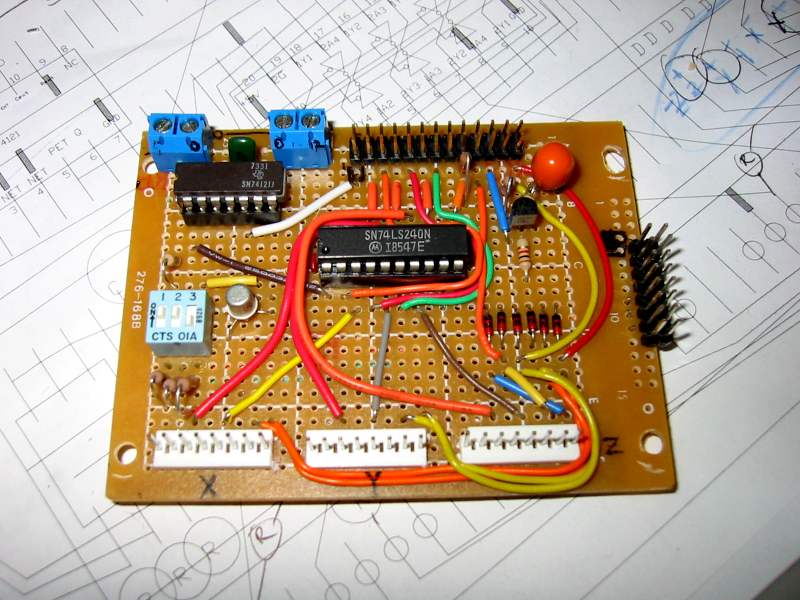
The process of converting them to classroom use began by reverse engineering the spindle control (since I was already quite familiar with the control of "step and direction" stepper drives). While I could have substituted a Dremel, it was pretty clear that the spindles (two per mill) were high-quality, brushless DC devices. Slowly (painfully tedious) I was able to discern the functions of necessary leads in the 16-wire cable coming out of the spindle control board, and utilize both on/off and speed control capabilities.
Having tested the spindle and three axis motion (with home and limit switches), I soldered up two permanent interface boards and modified the spindle orientation to a more intuitive Z direction. After a trip to Home Depot for some polystyrene, I started to have some fun...
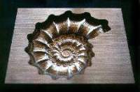
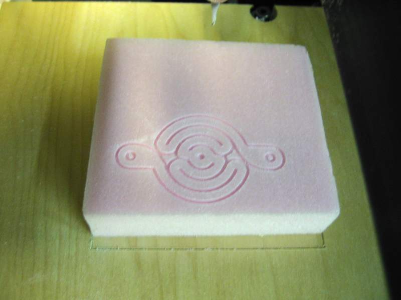
My first trials involved milling out the Science Museum of Minnesota's logo. Using a larger bit to do the roughing, and a 1/32" bit for the detail. (pic coming)
The next step was to see whether I could bridge the 3D modeling and animation software, Blender, to these machines. Blender is powerful FREEWARE, which is taught to students in the Learning Technologies Center at the SMM, in their animation classes. Blender, while perhaps not the easiest package to use, is an obvious choice for novices unwilling to shell out hundreds or thousands. The idea: students create a 3D surface in Blender, then save the data in a way that can allow a toolpath to be created, and fed to the mill-- virtual reality converted to real reality.
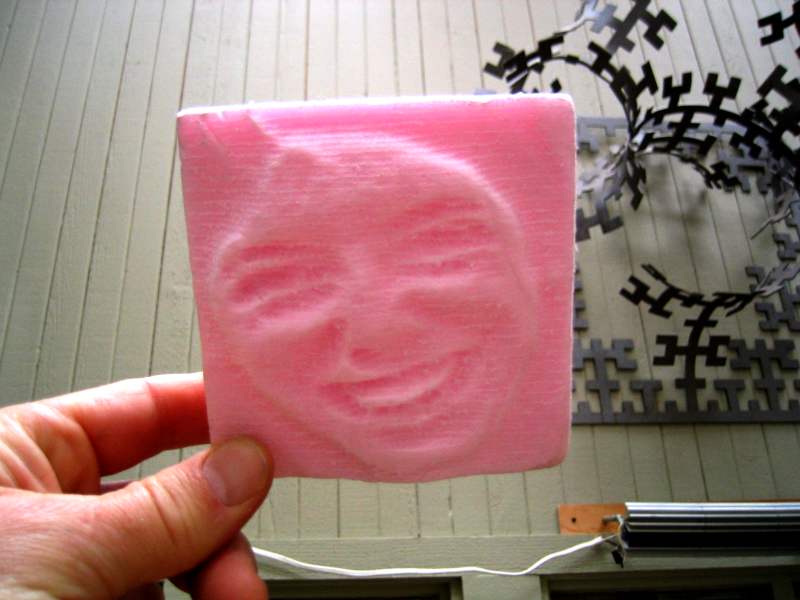
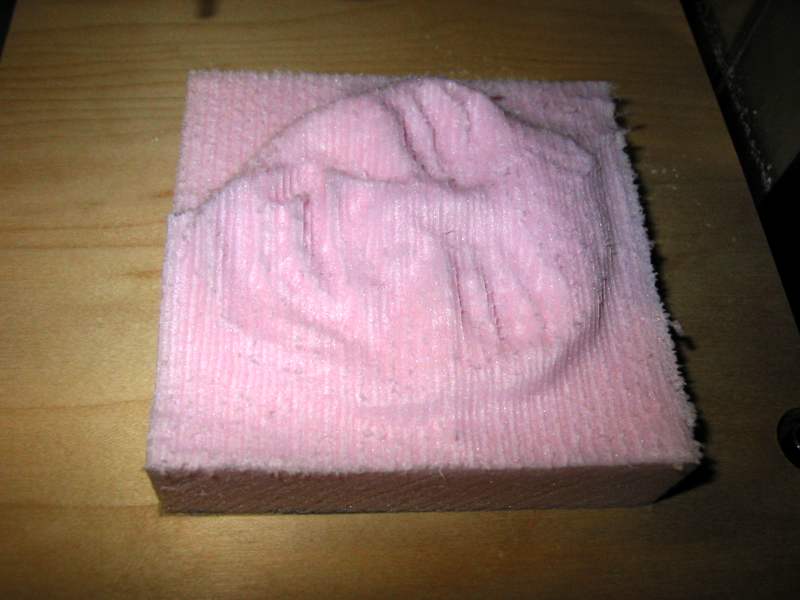
Unfortunately, Blender's export abilities did not match my requirements. Fortunately, Blender is able to run Python scripts. Unfamiliar with Python (and Blender) I hit Borders and bought a couple books. They enabled me to write a simple script that allows saving Blender meshes in an ordered fashion that I can turn into toolpaths. The first "proof of concept" examples involved mathematically "deformed" surfaces. And then, utilizing Blender's texture mapping facilily, the sculpting of a surface using the brightness of a bitmap. While not a true 3D rendering of my daughter's face, when viewed under the right lighting, it appears remarkably accurate.
To further the capabilities of these mills, I contacted the makers of Mastercam (CNC Software, Inc.). After explaining our goals, they graciously offered to donate a copy of their industry leading CAM software. With this sophisticated package, we should be able explore far more complex toolpath options. Hopefully, I will have examples in the near future...
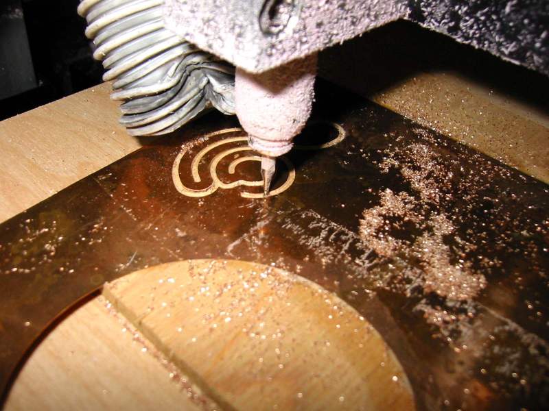
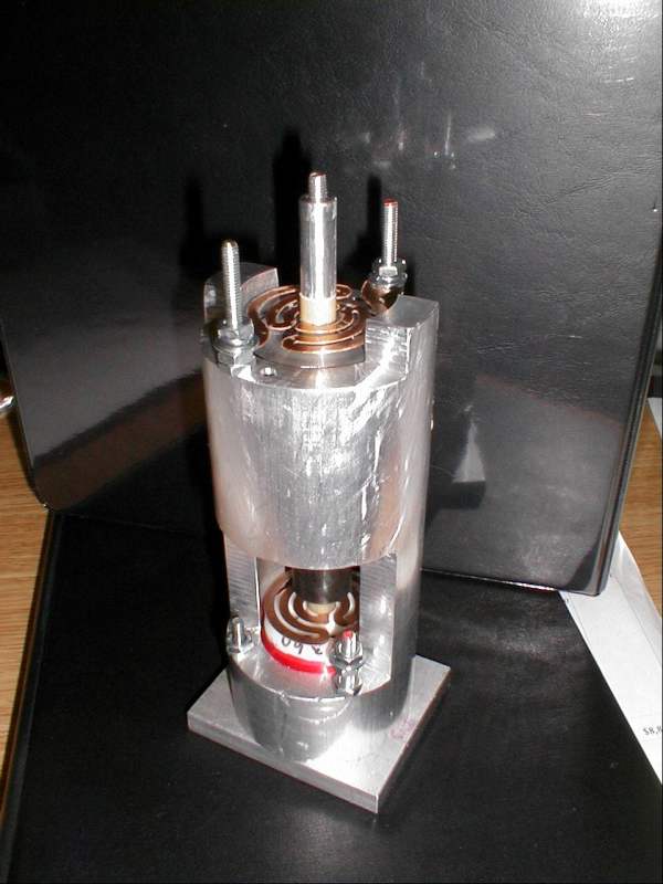
A recent call from a neighbor friend who is a physicist, illustrates the wonderfully unpredictable uses of DIY CNC: he creates highly specialized spectrophotometric equipment (Mössbauer Spec), and needed custom flexure plates (flat springs) to enable a portion of his apparatus to function properly. Because of their small size, this was a perfect job for the dental mill. He emailed the desired geometry, and after setting up the toolpath, I did a test pass. Then the real material (beryllium copper). He sent over this pic of the prototype apparatus.