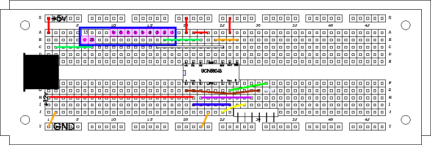
Here is the breadboard map of our single stepper motor driver circuit:
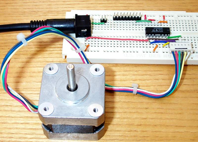
And here is a picture of the breadboard up to this point.
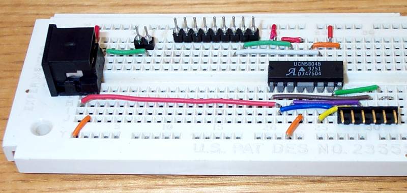
Placement of the PS connector is crucial-- the four pins must go into the first and second column of holes (E1,E2,F1,F2). This will ensure that 5+ is on the A1-D1 column, GND is on both the A2-D2 and F2-J2 columns, and 12+ is on the F1-J1 column. We will put a drop of Superglue on the bottom of this connector so that it does not come out every time we plug the PS into it.
After carefully checking to make sure that we have all the parts and jumpers properly in place, we will connect our stepper to the 6-prong connector (at J27-J32). Make sure the connection is made so that the motor's white and yellow leads are connected to the right side (J31,J32). Turn the motor shaft-- it should feel no different than before you made the connection.
Plug the PS's AC cord into a wall outlet, and then insert the PS's plug into the PS connector that has been glued to the breadboard. It only goes in one way (the arrow will be visible on top). Now try to turn the motor's shaft again-- it should be stuck tight! You may be able to overpower it into turning (this causes no harm), but there is an obvious difference. If the shaft turns easily, then something is wrong. Don't feel bad-- I rarely put together a circuit which works the first time! Disconnect the PS plug and carefully double check every connection. You will find the error if you are patient.
 You will notice that after a short while your motor will get very warm.
This is normal for stepper motors, but may surprise you if you don't know
this.
You will notice that after a short while your motor will get very warm.
This is normal for stepper motors, but may surprise you if you don't know
this.
OK-- if everything checks out (the motor shaft is stuck), we are now
ready to connect to the computer. But first, it is a good idea to
disconnect out PS from the breadboard, in case we put the 26-hole connector
on wrong. So, after removing power from the breadboard, connect the
26-hole connector to the 2+9 pins (just as with the Light-byte).
Now reconnect to the PS. Again the motor will be frozen in place.
Now we need to write a program to send step and direction bits to our
motor:
Start QBASIC, and type (in the program window):
OUT 888,2
OUT
888,0
Put your finger on the motor shaft and then push Sh-F5-- you
have just taken your first step!
Yes, it is rather small-- do it a couple times
to convince yourself that the shaft is really moving.
Now, let's use a loop to make lots of steps (steps1.bas):
CLS
INPUT "enter count value
for speed control: ", speed
FOR counter = 1 TO 400
OUT 888,2
OUT 888,0
FOR zz = 1 TO speed: NEXT
NEXT counter
Run the program (Sh-F5) and try a count value of 500. You should see the shaft take 1 complete rotation. Try it a few times, and pay careful attention to the starting and final position of the flat spot on the shaft (they should be exactly the same). Try different count values-- the lower, the faster it goes (remember, the computer must count up to this number in between every step). You will find a value that is too low-- the motor just can't step that fast. This causes no harm to the motor or the computer, but of course this "misstepping" causes position errors and we will want to avoid it in the future when we are building robots.
How can we make it go in the other direction? Think about that direction bit. It is assigned to bit #0 (STEP is on bit #1). In our program, we have left it off the whole time-- OUT 888,2 can be thought of as OUT 888, 0+2 . But what if we try OUT 888,1+2 -- go ahead, modify the program and run it. The shaft should complete 1 rotation in the opposite direction now.
Finally, let's do both directions, 10 times (steps2.bas):
CLS
INPUT "enter count value
for speed control: ", speed
FOR repetition = 1 to 10
FOR counter = 1 TO 400
OUT 888,2
OUT 888,0
FOR zz = 1 TO speed: NEXT
NEXT counter
FOR counter = 1 TO 400
OUT 888,3
OUT 888,0
FOR zz = 1 TO speed: NEXT
NEXT counter
NEXT repetition
Notice that (if you haven't chosen a counter value too low) the shaft position at the start and end of the run is the same. This is because we have asked the motor to make full rotations only. But if you look at the program you will notice that our program commanded the motor to take 400 steps (not 200). The reason is that we are running in "half-step" mode-- an option of the 5804b chip. Although our motor is designed to take a step of 1.8 degrees (200 steps/rev), this applies only when it is run in "full-step" mode. The 5804b chip can run in this mode, but I always choose half-step because it is smoother (results in smaller motion pixels). Even though we will actually be taking half-steps, I will refer to these simply as steps.