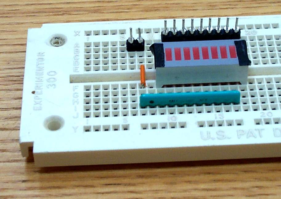
Light-byte before... and after connection to the parallel port.
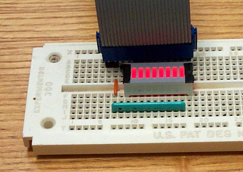
Remember to be particularly careful to make sure that the 26-hole connector goes onto the 9+2 pins sticking up from the breadboard!
Since the 8 data bits from the parallel port ride on wires that are
lined up next to each other (#2-#9), this makes for a very efficient layout
of parts on our breadboard:
Light-byte before...
and after connection to the parallel port.
Remember to be particularly careful to make sure that the 26-hole connector
goes onto the 9+2 pins sticking up from the breadboard!
Now, lets trace out the circuit's paths:
CLS
INPUT "enter count value
for speed control: ", speed
FOR counter = 1 TO 10
OUT 888,1
FOR zz = 1 TO speed: NEXT
OUT 888,0
FOR zz = 1 TO speed: NEXT
NEXT
Go ahead and run it. You should see LED 0 blinking. Now how can we get the other LED's to blink? Well there are lots of ways-- but probably the simplest is to change OUT 888,1 to OUT 888,255. Try it! Hopefully this should start making sense, since 255 is equal to 11111111 (all bits on) in base 2.
It's nice to see all our 8 light-bits working, but this is not much more interesting than a single blinking LED. Remember that we can turn on and off each bit independantly of its neighbors. So let's create a program that blinks each LED in succession. We'll call it march1.bas:
CLS
INPUT "enter count value
for speed control: ", speed
FOR counter = 1 TO 10
OUT 888,1
FOR zz = 1 TO speed: NEXT
OUT 888,2
FOR zz = 1 TO speed: NEXT
OUT 888,4
FOR zz = 1 TO speed: NEXT
OUT 888,8
FOR zz = 1 TO speed: NEXT
OUT 888,16
FOR zz = 1 TO speed: NEXT
OUT 888,32
FOR zz = 1 TO speed: NEXT
OUT 888,64
FOR zz = 1 TO speed: NEXT
OUT 888,128
FOR zz = 1 TO speed: NEXT
NEXT
Go ahead and try it. You should see a nice march of LED lightings repeated 10 times. (Why is it unnecessary to have OUT 888,0 statements to turn the LED's off after they have been on? -- hint: take a look at the bit values in this table)
When writing a program, there are almost always many ways to accomplish the same task. Often, the goal of the programmer is to write code which is efficient-- meaning that the task is accomplished using the least lines of code. March1.bas does it's job OK, but are there other ways? How about march2.bas:
CLS
INPUT "enter count value
for speed control: ", speed
FOR counter = 1 TO 10
OUT 888,2^0
FOR zz = 1 TO speed: NEXT
OUT 888,2^1
FOR zz = 1 TO speed: NEXT
OUT 888,2^2
FOR zz = 1 TO speed: NEXT
OUT 888,2^3
FOR zz = 1 TO speed: NEXT
OUT 888,2^4
FOR zz = 1 TO speed: NEXT
OUT 888,2^5
FOR zz = 1 TO speed: NEXT
OUT 888,2^6
FOR zz = 1 TO speed: NEXT
OUT 888,2^7
FOR zz = 1 TO speed: NEXT
NEXT
OK, it's not more efficient. But it is an improvement because it is easier to see the "marching" of the bit numbers (0 to 7). This counting of exponents suggests another idea-- march3.bas:
CLS
INPUT "enter count value
for speed control: ", speed
FOR counter = 1 TO 10
FOR bit = 0 TO 7
OUT 888,2^bit
FOR zz = 1 TO speed: NEXT
NEXT bit
NEXT counter
Ahh, much better. Now we are using two loops-- one within the other. The inner loop steps the exponent called "bit" through the values 0 to 7 (turning on the corresponding LED's as it does). The outer loop simply repeats this process 10 times, as we have seen before.
Although the Light-byte may be simple, you may be surprised by how many interesting and different ways you can sequence the LED's. Keep in mind that for simplicity, all the examples thus far have kept the same timing for each LED, but this need not be so. Try out a few of the examples that are provided. As always, you will learn far more by trying to create new programs by modifying the examples.
Of course, our Light-byte software can be used to control different
hardware than just LED's...